Advance ES400 XLP Parts Manual: An Overview
This manual, form 56042641, details parts for ES300 ST, XP, and ES400 XLP models. It includes ladder diagrams and revisions dating from July 2015 to May 2016.
The Advance ES400 XLP is a powerful 12-gallon carpet extractor designed for professional cleaning applications. This parts manual, identified as form number 56042641, serves as a crucial resource for maintenance, repair, and parts identification. It specifically covers the ES300 ST, ES300 XP, and ES400 XLP models, offering detailed breakdowns of each component.

Understanding the intricacies of the ES400 XLP requires access to accurate and up-to-date information. This manual provides precisely that, including ladder diagrams (referenced in form 56042642) to aid in electrical system troubleshooting. Revisions were made as recently as May 2016, ensuring the information reflects the latest specifications. Note that parts availability may vary, as indicated in associated documentation.
Scope of the Parts Manual
This Advance ES400 XLP parts manual (form 56042641) comprehensively details components for the ES300 ST, ES300 XP, and ES400 XLP carpet extractors. Its primary function is to facilitate accurate parts ordering and efficient machine repair. The manual includes detailed parts lists, referencing specific item numbers and quantities needed for various repairs.
Furthermore, it incorporates ladder diagrams – specifically 16ST and 16XP-18XLP – to assist technicians in understanding the electrical system’s configuration. Revisions occurred in July 2015, July 2016, and May 2016, reflecting updates and corrections. It’s important to acknowledge that this manual is for reference only, and parts availability isn’t guaranteed, as noted in accompanying documentation regarding replacement parts.
Essential Components & Parts
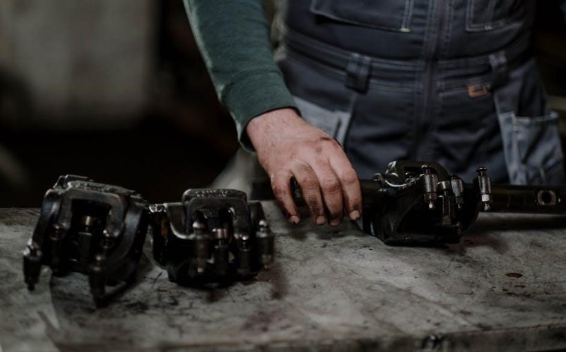
Key parts include the pump system, vacuum motor, electrical components (CB1, D1, L1), solution delivery system, and the brush system with its motor (M3).
Pump System Parts
The pump system is a critical element of the Advance ES400 XLP, responsible for fluid delivery during cleaning operations. Detailed breakdowns of the pump assembly are available within the parts manual (Form No. 56042641). Specific attention should be given to the pump motor, ensuring correct specifications for optimal performance. The manual provides resources for identifying and replacing worn or damaged pump components.
Understanding the pump’s functionality and associated parts is essential for effective maintenance and repair. Refer to the parts list for accurate identification of each component, facilitating efficient parts ordering and minimizing downtime. Proper pump maintenance contributes significantly to the overall longevity and effectiveness of the ES400 XLP carpet extractor.
Pump Motor Specifications
The Advance ES400 XLP pump motor is a vital component, directly impacting cleaning performance. While specific motor details aren’t explicitly provided in the snippets, the parts manual (Form No. 56042641) is the definitive source for these specifications. Proper motor function relies on correct voltage and amperage, ensuring adequate fluid pressure and flow.
When replacing the pump motor, it’s crucial to match the original specifications to maintain optimal performance. Referencing the parts list within the manual will guarantee compatibility. Troubleshooting pump issues often begins with verifying the motor’s operational status. Maintaining the pump motor contributes to the overall efficiency and longevity of the ES400 XLP cleaning system.
Pump Assembly Breakdown
The Advance ES400 XLP pump assembly, detailed within parts manual 56042641, is a complex system requiring careful attention during maintenance and repair. The assembly includes the pump motor (referenced as ‘M’ in ladder diagrams), alongside various hoses, fittings, and the pump housing itself.
Disassembly should follow a logical sequence, documenting each step to ensure correct reassembly. The manual’s parts list provides itemized components with corresponding reference numbers. Inspecting seals and connections for wear or damage is crucial during breakdown. Proper lubrication of moving parts is essential for smooth operation. A complete understanding of the pump assembly is vital for effective troubleshooting and parts replacement, maximizing the machine’s cleaning capability.
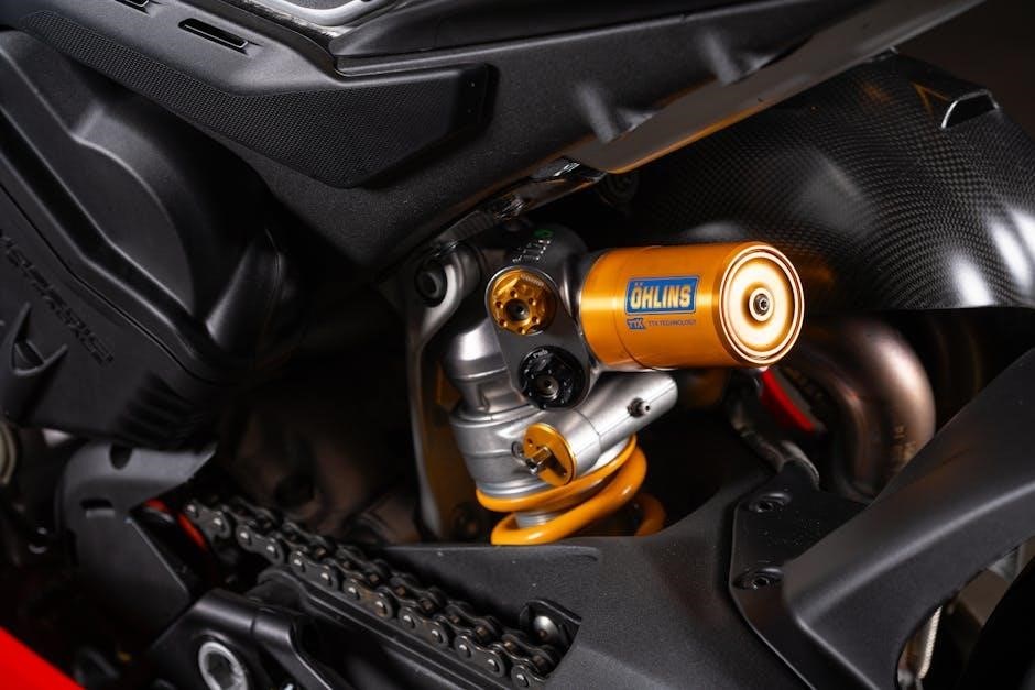
Vacuum Motor & Components
The vacuum system within the Advance ES400 XLP, as outlined in parts manual 56042641, is critical for effective soil extraction. Key components include the vacuum motor (designated ‘M2’ in the ladder diagram), the vacuum fan, and the housing that contains them. Maintaining optimal vacuum performance is essential for achieving thorough cleaning results.
The manual details the specifications and potential replacement parts for each component. Regular inspection of the vacuum fan for debris and damage is recommended. Proper sealing of the vacuum housing is vital to prevent air leaks and maintain suction power. Troubleshooting vacuum issues often involves checking the motor’s electrical connections and ensuring the fan spins freely. Referencing the parts list ensures accurate component identification during repairs.
Vacuum Motor Details
The Advance ES400 XLP’s vacuum motor, identified as ‘M2’ within the wiring diagrams (specifically 16ST), is a crucial element of the machine’s cleaning power. While specific motor specifications aren’t explicitly detailed in the provided snippets, the parts manual (form 56042641) facilitates identifying the correct replacement unit.
Troubleshooting vacuum motor issues often begins with verifying electrical connectivity – checking wiring colors (Green/Yellow) as indicated in the ladder diagram. The motor’s functionality is directly linked to the overall vacuum system’s performance. Replacement should only be undertaken by qualified personnel, ensuring correct voltage and amperage matching. Proper motor function guarantees optimal suction for effective carpet and upholstery cleaning, contributing to the machine’s overall efficiency.
Vacuum Fan & Housing
The vacuum fan, working in conjunction with the vacuum motor (M2), generates the suction necessary for the Advance ES400 XLP’s cleaning process. Although the provided excerpts don’t offer detailed specifications for the fan itself, the parts manual (form 56042641) is the primary resource for identifying compatible replacement parts.
The fan housing is integral to directing airflow and maximizing vacuum efficiency. Damage to either the fan blades or the housing can significantly reduce suction power. Inspection during maintenance should include checking for obstructions and structural integrity. Proper assembly, as illustrated in the parts breakdown, is crucial for optimal performance. Maintaining a clear airflow path ensures effective debris removal and prolongs the life of the vacuum system.

Electrical System Parts
The Advance ES400 XLP’s electrical system relies on several key components, detailed within parts manual form 56042641. Critical parts include the main power switch, identified with wiring connections (BLK, WHT), and a 5 Amp circuit breaker (CB1 ‒ part number 56265550) providing essential overload protection.
A 35 Amp rectifier (D1 ⎯ part number 56265103) is also vital for converting AC to DC power. The manual’s ladder diagrams (16ST, 16XP-18XLP) illustrate the wiring configuration for these components. Safe replacement of electrical parts requires disconnecting the machine from power and adhering to all safety precautions. Proper functioning of these parts ensures reliable operation and prevents potential hazards.
Main Power Switch & Wiring
The main power switch, crucial for controlling the Advance ES400 XLP, features specific wiring configurations as detailed in form 56042641. Wiring connections are identified as Black (BLK) and White (WHT), serving as key identifiers during maintenance or replacement. The ladder diagram (16ST) visually represents these connections within the overall electrical system.
Proper functionality of this switch is paramount for safe operation. Disconnecting power before servicing is essential. The switch’s role is to completely isolate the machine from the power source. Referencing the parts manual ensures correct wiring and component identification, preventing electrical hazards and maintaining the machine’s operational integrity. Always verify connections before restoring power.
Circuit Breaker Information (5 Amp ‒ CB1)
The 5 Amp circuit breaker, designated as CB1 in the Advance ES400 XLP parts list (form 56042641), is a vital safety component. Its primary function is to protect the electrical system from overcurrents, preventing damage to components and potential fire hazards. The breaker is identified with part number 56265550. It’s positioned within the machine’s electrical circuit, as illustrated in the ladder diagram (16ST).
Should the CB1 breaker trip, it indicates an electrical overload. Before resetting, identify and rectify the cause of the overload. Repeated tripping suggests a more significant issue requiring professional attention. Replacement should only be done with an equivalent 5 Amp breaker to maintain safety standards and ensure proper system protection. Always disconnect power before any maintenance.
Rectifier Details (35 Amp ⎯ D1)
The 35 Amp rectifier, identified as D1 within the Advance ES400 XLP’s parts documentation (form 56042641), plays a crucial role in converting alternating current (AC) to direct current (DC). This DC power is essential for operating various components within the machine, including motors and solenoids. The specific part number for this rectifier is 56265103. It’s visually represented and its placement detailed within the machine’s ladder diagram, specifically referenced in the parts list.
A malfunctioning rectifier can lead to inconsistent performance or complete failure of dependent systems. When replacing D1, ensure the replacement unit matches the 35 Amp specification. Disconnect the power supply before any maintenance or replacement procedures to avoid electrical shock. Proper functionality of D1 is critical for the overall operation of the ES400 XLP.
Solution Delivery System
The solution delivery system within the Advance ES400 XLP is responsible for accurately mixing and dispensing cleaning solution during operation. A key component is the 115V Solenoid Valve (L1), part number 56265746, which controls the flow of solution from the solution tank. This valve is activated by the machine’s control system to regulate solution application. The system also includes the solution tank itself, along with associated hoses, filters, and spray nozzles – all vital for effective cleaning.
Proper functioning of the solenoid valve (L1) is crucial; failures can result in either no solution delivery or continuous, uncontrolled flow. Refer to the parts list (form 56042641) for detailed breakdowns and component identification within this system.
Solenoid Valve (115V ‒ L1)
The 115V Solenoid Valve, designated as L1 in the wiring diagrams, is a critical component of the Advance ES400 XLP’s solution delivery system. Identified by part number 56265746, this valve regulates the flow of cleaning solution from the tank to the spray nozzles. Its operation is electrically controlled, opening and closing based on signals from the machine’s control circuitry.
Troubleshooting steps for issues related to solution delivery should always begin with verifying the solenoid valve’s functionality. Check for proper voltage supply and inspect the valve for any physical damage or obstructions. Replacement is straightforward, referencing the parts list (form 56042641) ensures the correct component is used. A faulty L1 valve will prevent proper solution dispensing.
Solution Tank & Components
The Advance ES400 XLP’s solution tank is integral to the cleaning process, holding the water and cleaning solution mixture. While the manual doesn’t detail specific tank part numbers, it’s crucial for maintaining optimal performance. Associated components, though not individually listed extensively, include fill caps, strainers, and connecting hoses that deliver solution to the solenoid valve (L1).
Regular inspection of the tank for cracks or leaks is essential. Ensure the strainer is clear of debris to prevent clogging of the solution delivery system. Proper maintenance extends the life of the pump and solenoid valve. Referencing the overall parts list (form 56042641) can aid in identifying compatible hoses and fittings for repair or replacement needs.
Brush System & Motor
The brush system, powered by motor M3, is a critical component for effective carpet cleaning in the Advance ES400 XLP. The parts manual (form 56042641) identifies M3 as the brush motor, though detailed specifications aren’t explicitly provided within the excerpt. The brush assembly itself comprises the brush roller, housing, and associated mounting hardware.
Maintaining the brush system involves regular inspection for wear and tear on the brush bristles and ensuring the motor operates smoothly. Replacement brushes are essential for continued cleaning performance. While the manual doesn’t list individual brush component part numbers, referencing the complete parts list is recommended. Proper brush maintenance contributes significantly to the overall longevity and effectiveness of the machine.
Brush Motor Specifications (M3)
Unfortunately, the provided excerpts from the Advance ES400 XLP parts manual (form 56042641) do not detail specific technical specifications for the brush motor, designated as M3. The documentation identifies M3 simply as the “MOTOR, BRUSH” within the ladder diagram and parts list.
Information such as voltage, amperage, horsepower, or RPM is absent from these snippets. To obtain precise specifications – including potential replacement motor part numbers – consulting the complete Advance parts list manual is crucial. Further research may involve contacting Nilfisk-Advance directly or a qualified service technician specializing in this equipment. Accurate motor specifications are vital for correct replacement and optimal performance.
Brush Assembly & Components
The provided excerpts from the Advance ES400 XLP parts manual (form 56042641) offer limited detail regarding the brush assembly itself. The documentation primarily references “MOTOR, BRUSH” (M3) within the electrical system’s ladder diagram. A comprehensive breakdown of individual brush components – such as brush rollers, housings, or related hardware – isn’t present in these sections.
The complete parts list manual would be necessary to identify specific part numbers for each component of the brush assembly. This would include details on brush roller materials, dimensions, and compatibility. For detailed assembly instructions or diagrams, referencing the operator’s manual alongside the parts list is recommended. Proper brush assembly ensures effective carpet cleaning performance.
Specific Part Numbers & Identification
Form 56042641 lists key parts like circuit breaker CB1 (56265550), rectifier D1 (56265103), and solenoid valve L1 (56265746).
Identifying Parts Using the Parts List (Form No. 56042641)
Utilizing Form No. 56042641 is crucial for accurate parts identification within the Advance ES300 ST, ES300 XP, and ES400 XLP carpet extractor series. This comprehensive parts list, revised as recently as May 2016, provides a detailed breakdown of each component, cross-referenced by a unique item and reference number.
Locate the specific part you require within the list, noting its corresponding reference number (Ref. No.). This number is essential when ordering replacements. The manual also details quantities (Qty) for each part per machine. Key components, such as the 5 Amp Circuit Breaker (CB1 ‒ 56265550) and the 35 Amp Rectifier (D1 ⎯ 56265103), are clearly identified. Always verify the revision date to ensure you are using the most current information.
Ladder Diagram Interpretation (16ST, 16XP-18XLP)
The ladder diagrams, specifically 16ST and 16XP-18XLP, are vital for understanding the electrical system of the Advance ES300 ST, ES300 XP, and ES400 XLP models. These diagrams illustrate the wiring connections and circuitry, aiding in troubleshooting and parts replacement. They depict components like the main power switch, pump motor (M1, M2), vacuum motor, brush motor (M3), solenoid valve (L1), and the circuit breaker (CB1).
Understanding the color coding of wires (e.g., GRN/YEL, WHT, BLK, TAN, RED, VIO) is essential for tracing circuits. The diagrams show how these components interact, including the flow of power and control signals; Refer to Form No. 56042642 for detailed ladder diagram views, spanning pages 14-15.
Key Part Numbers for ES300 ST, ES300 XP, and ES400 XLP
This section lists crucial part numbers for the ES300 ST, ES300 XP, and ES400 XLP models, simplifying the parts ordering process. Key components and their corresponding numbers include the Circuit Breaker (CB1) – 56265550 (5 Amp), and the Rectifier (D1) – 56265103 (35 Amp). The Solenoid Valve (L1), operating at 115V, is identified as part number 56265746.
These numbers, documented in Form No. 56042641 (revised July 2015, May 2016), are essential for accurate parts requests. Note that availability may vary, as indicated in related documentation. Utilizing these part numbers ensures correct replacements, maintaining the functionality of your Advance carpet extractor. Always double-check compatibility with your specific model variant.

Troubleshooting & Parts Replacement
Common issues are addressed with corresponding parts lists; always prioritize safety precautions when replacing components, referencing the manual for guidance and proper procedures.
Common Issues & Corresponding Parts
Addressing operational difficulties begins with identifying the problem. Loss of vacuum often points to the vacuum motor (referenced in the parts list) or a blockage within the vacuum fan and housing assembly. Reduced cleaning performance may stem from a failing pump motor, requiring inspection and potential replacement – consult specifications for correct matching.
Electrical faults, such as a non-functioning power switch, necessitate checking the main power switch and associated wiring. A tripped circuit breaker (CB1, 5 Amp) indicates an overload; reset after addressing the cause. Rectifier (D1, 35 Amp) failure impacts power delivery. Solution delivery issues often involve the solenoid valve (L1, 115V) or obstructions in the solution tank components. Brush motor (M3) problems affect agitation. Refer to form 56042641 for specific part numbers.
Safety Precautions for Parts Replacement
Prioritize safety during all maintenance procedures. Always disconnect the machine from the main power source before commencing any parts replacement to prevent electrical shock. Wear appropriate personal protective equipment, including safety glasses and gloves. Be mindful of sharp edges and potential pinch points during disassembly and reassembly.
When handling electrical components like the rectifier (D1) or circuit breaker (CB1), exercise extreme caution. Ensure proper grounding to avoid static discharge. When working with the solution tank, avoid contact with cleaning solutions. Properly dispose of any damaged parts according to local regulations. Refer to the parts list (form 56042641) for correct component identification and consult a qualified technician if unsure about any procedure.
Manual & Documentation Resources
The complete parts list manual (form 56042641) is readily accessible, with revisions noted for 7/2015, 7/2016, and 5/2016 availability;
Accessing the Complete Parts List Manual
The comprehensive parts list manual for the Advance ES400 XLP, along with compatible ES300 ST and ES300 XP models, is identified by form number 56042641. This crucial document provides detailed schematics, exploded views, and part numbers essential for maintenance and repair. It’s important to note that while the manual serves as a valuable reference, parts availability isn’t guaranteed due to potential obsolescence or supply chain limitations.
The manual includes ladder diagrams (referenced in form 56042642) for electrical system troubleshooting, specifically for 16ST and 16XP-18XLP machine variants. Users should consult the revision history – updates were issued in July 2015, July 2016, and May 2016 – to ensure they are referencing the most current information. Accessing this manual is the first step in effectively managing parts identification and replacement for your Advance carpet extractor;
Revision History of the Parts Manual (7/2015, 7/2016, 5/2016)
The Advance ES400 XLP parts manual, form number 56042641, underwent several revisions to ensure accuracy and reflect potential component updates. The initial release occurred in July 2015, establishing the foundational parts list for the ES300 ST, ES300 XP, and ES400 XLP models. A subsequent revision followed in July 2016, incorporating feedback and addressing any identified discrepancies.
Further refinements were implemented with a revision dated May 2016, potentially including updates to part numbers, diagrams, or troubleshooting guidance. It’s crucial to verify the date of the manual being used – July 2015, July 2016, or May 2016 – to guarantee compatibility with the specific machine and ensure accurate parts identification. These revisions demonstrate a commitment to maintaining a reliable resource for service and repair.
Availability of Parts
Regarding parts for the Advance ES400 XLP, ES300 ST, and ES300 XP models, availability can vary significantly. While the parts list manual (form 56042641) serves as a comprehensive reference, it’s important to note a disclaimer stating that “parts may not be available.” This suggests potential obsolescence or limited stock for certain components.
Due to the age of these machines, sourcing specific parts might require contacting specialized cleaning equipment suppliers or exploring used/refurbished options. Checking with Nilfisk-Advance directly, or authorized service centers, is recommended. Be prepared to provide the exact part number and model information when inquiring. Proactive maintenance and stocking critical wear items can mitigate potential downtime caused by parts scarcity.